The problem
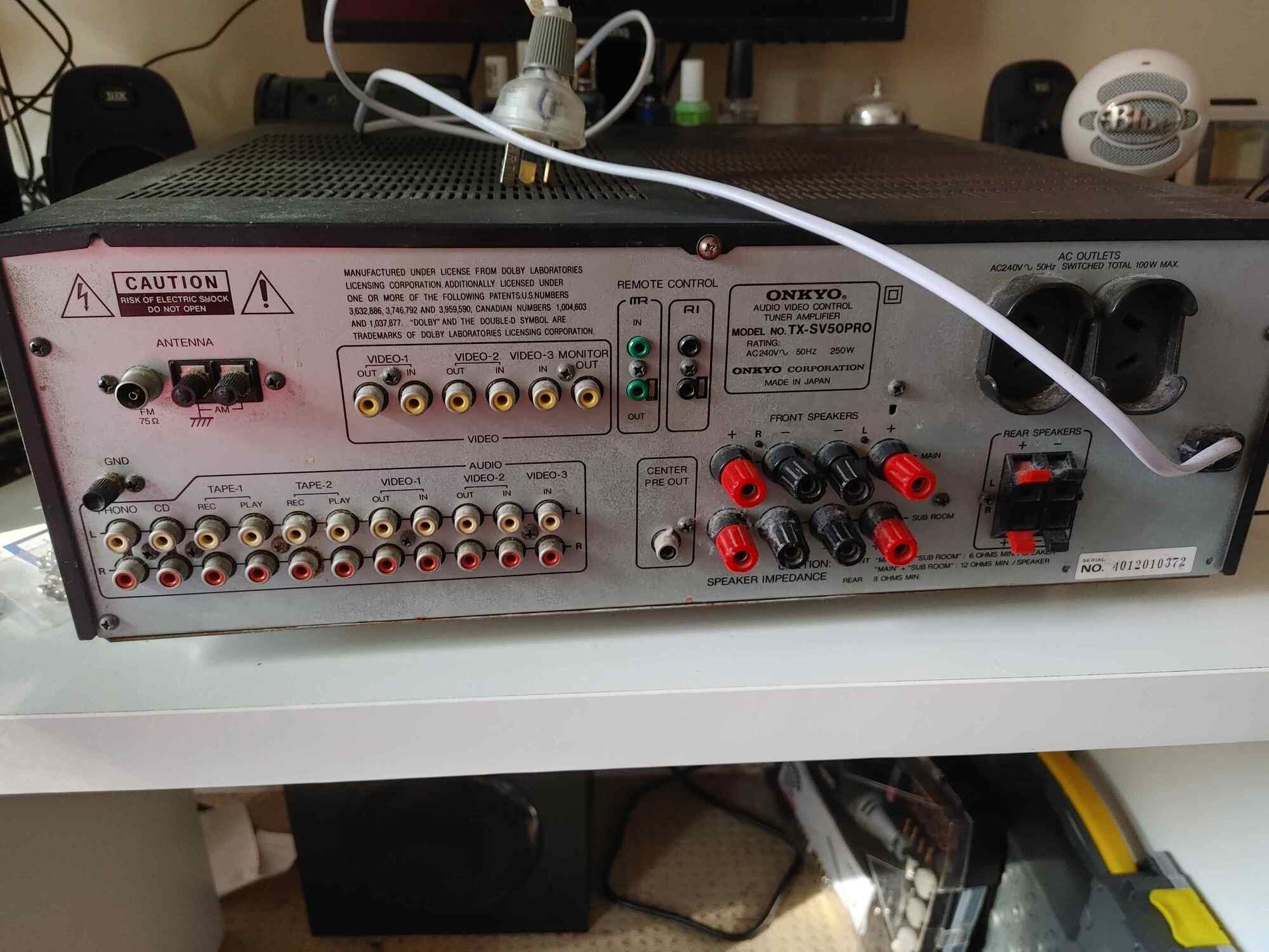
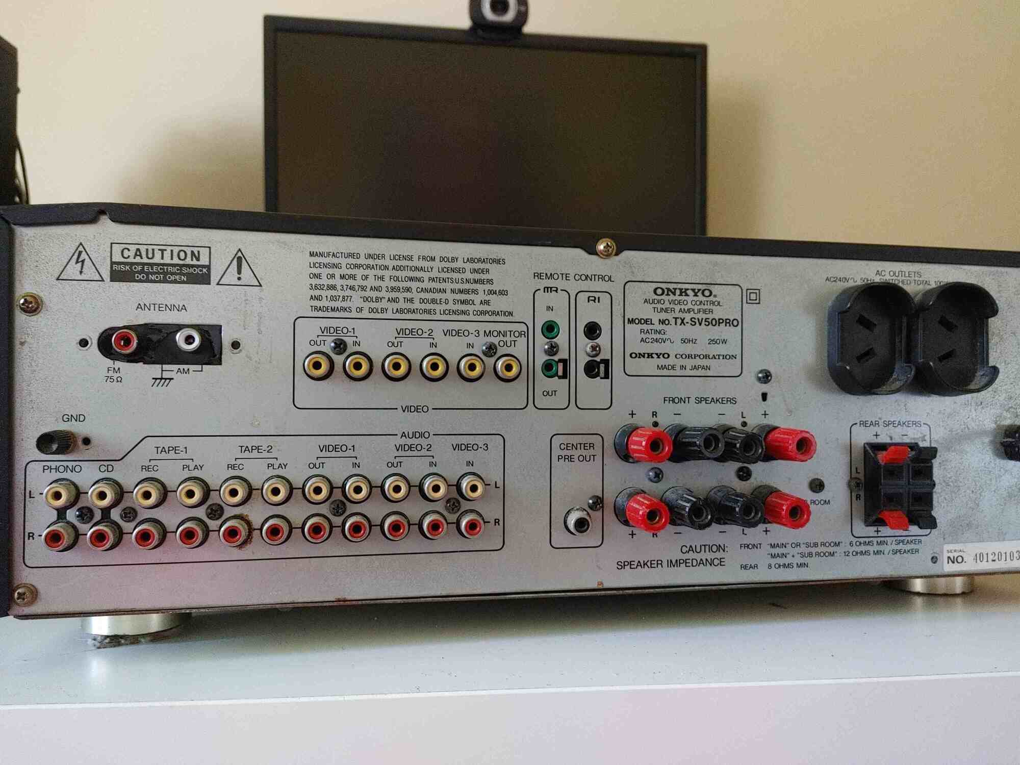
So I have this AV receiver, the Onkyo TX-SV50PRO.
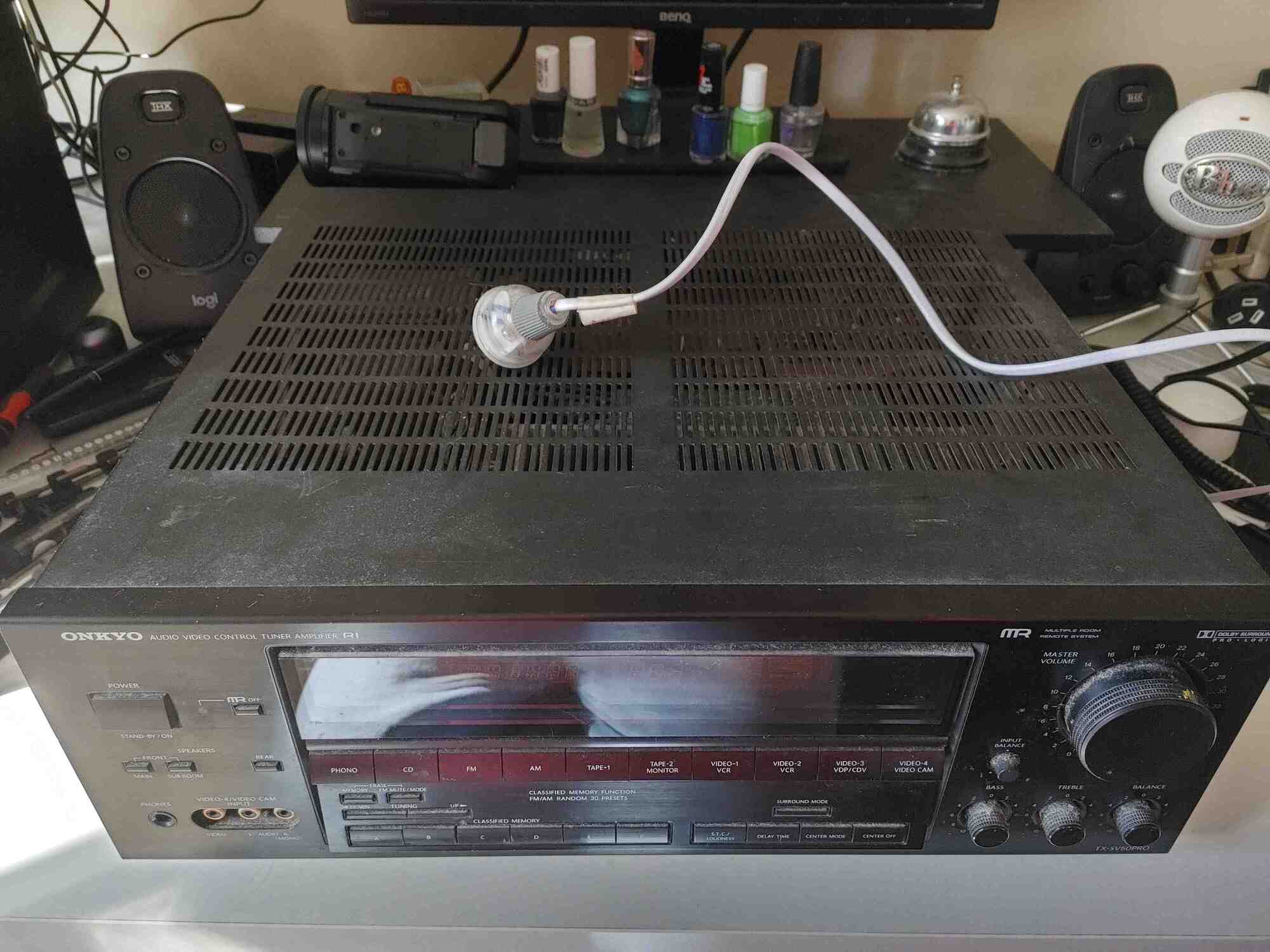
It’s pretty good, for its time. It’s from 1991, so it doesn’t have video better than composite, but I only use it for processing audio anyway, so it’s not like that matters. However, there is one issue that I’ve had with it for ages: the radio tuner doesn’t work.
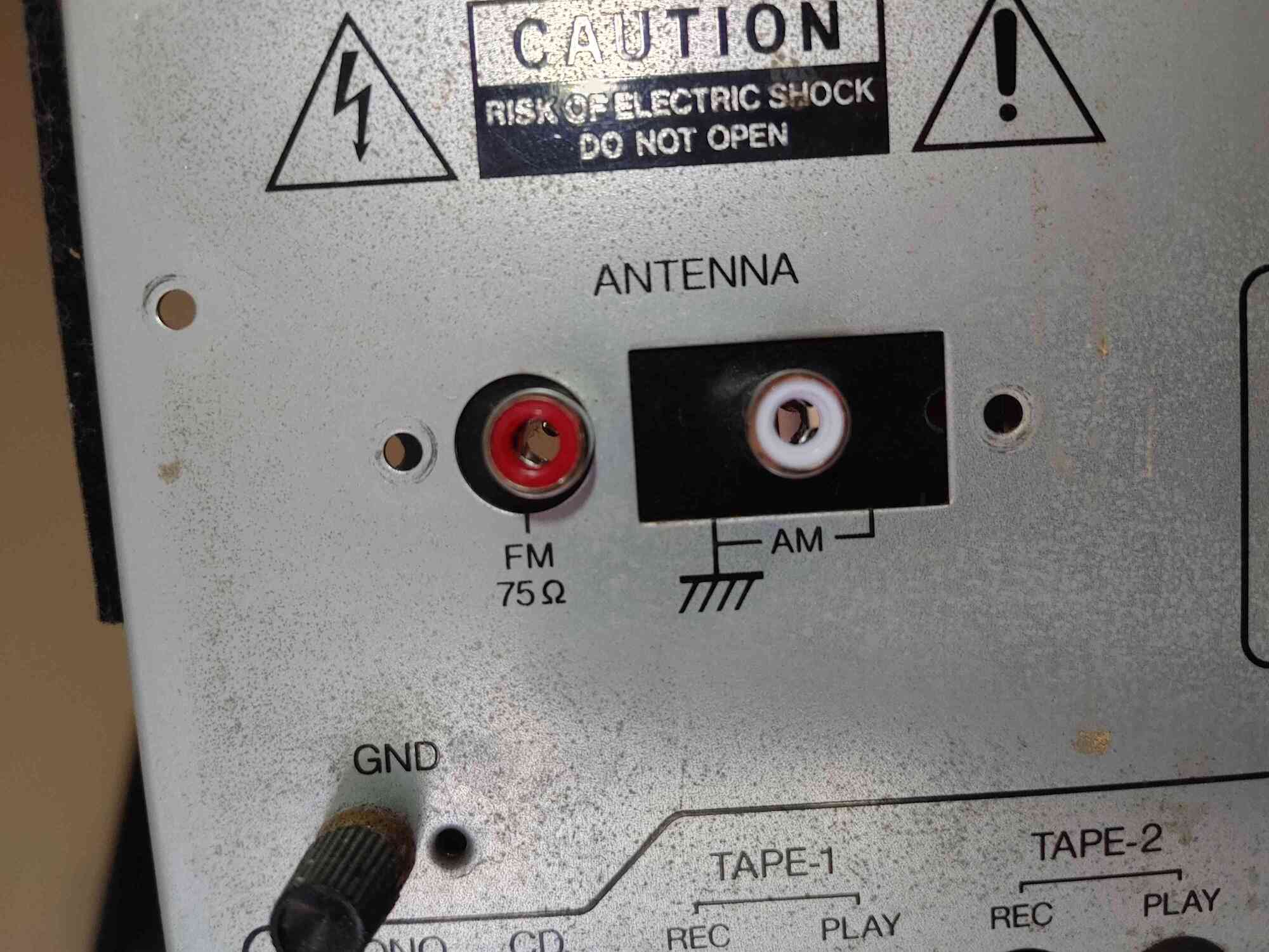
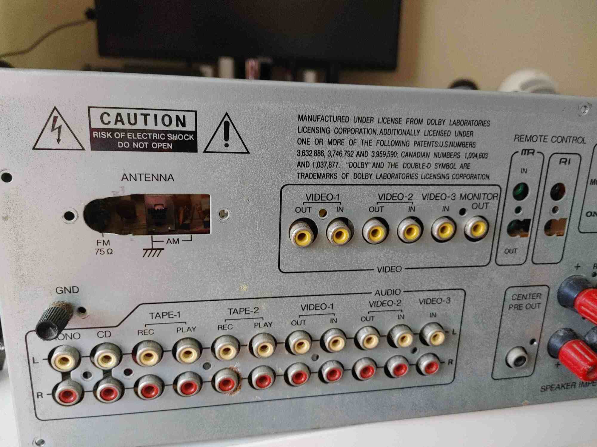
Now, granted, there’s a couple of reasons why it might not work, but I only care about one reason: the antenna input on the back.
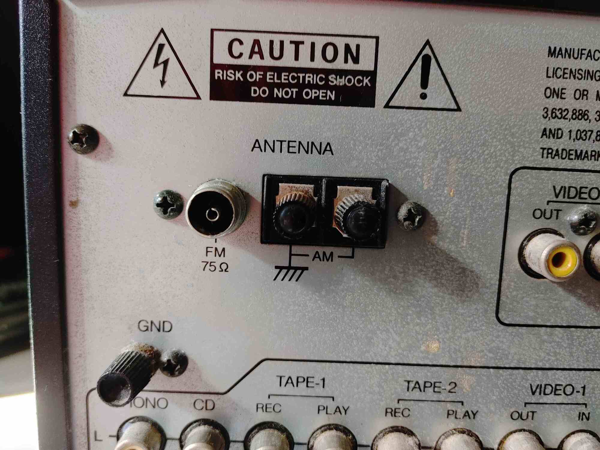
That is an F connector, which is normally meant for television signals. It can be used for radio antennas as well, however the instruction manual for plugging in the antennas is… vague.
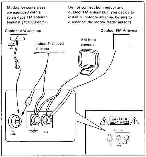
I’ve never seen an FM antenna with an F connector and a ground lead, and the AM loop antenna I have only has a single cable, not two. There was no obvious way to get them connected, and nothing I tried ever worked.
Fortunately, I have a standalone radio tuner!
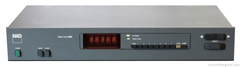
Behold, the NAD 4225. I love this thing, it’s super pretty, and unlike the AV receiver, it actually works. Works great, actually. When using this, I can hear FM signals no problem. AM signals are a lot harder, but my location has pretty bad AM radio signal anyway.
So what’s the problem, you ask? Just connect the external tuner to the receiver and call it a day, right?
Yeah, well. Not so fast.
Turns out that this receiver does not have any way of connecting the tuner to it. True, I could plug it into the CD input, as I’m not using that due to currently lacking a CD player, but it wouldn’t feel right. I want to switch the receiver to FM/AM and use the external tuner as the sound input, dammit!
So I started thinking, and then I was thinking more, and then I looked at the schematics for the receiver.
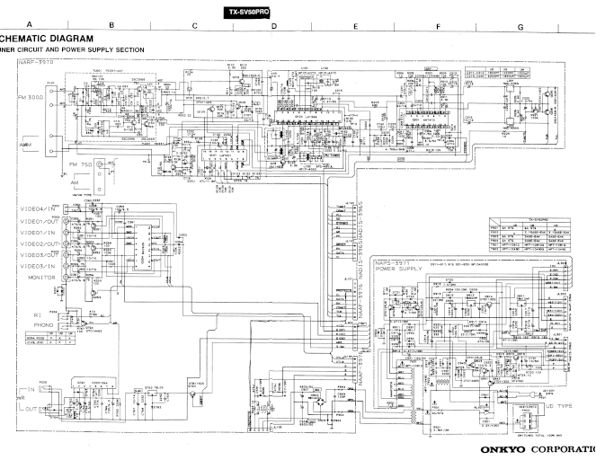
It’s pretty complicated, but with the help of the block diagram included in the service manual, I realised that it might be possible to bypass the tuner circuit entirely. I might be able to install a couple of RCA inputs on the back, and then the receiver would think that was the output from the tuner. With a bit of luck, I’d actually be able to remove the antenna inputs, and essentially add an additional input.
Time to get to work!
The tinkering
There’s a bunch of screws on the side, as there always are with these things, and naturally not all of them will be used by the time I’m finished. It’s weird how that happens.
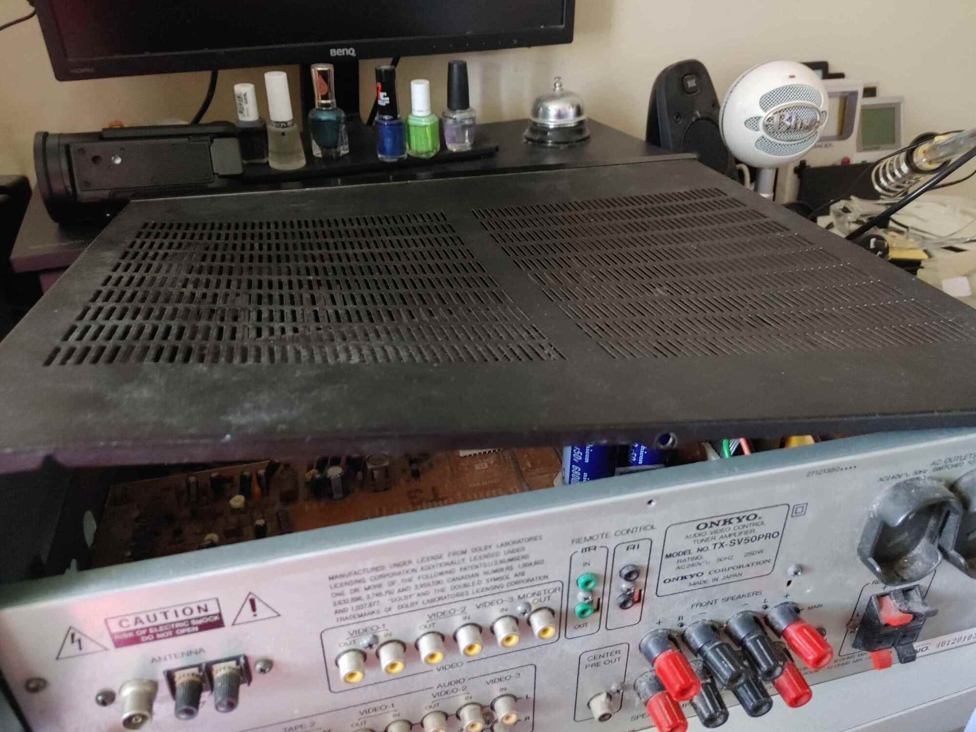
It was weirdly quite difficult to get the top of the case off after this, I had to really pull at it an awful lot. Fortunately, it did come away eventually.
Yeah, I’m not planning on actually doing much work on the inside of this, at least when it comes to cleaning. There’s a lot in there, and I just can’t be bothered.
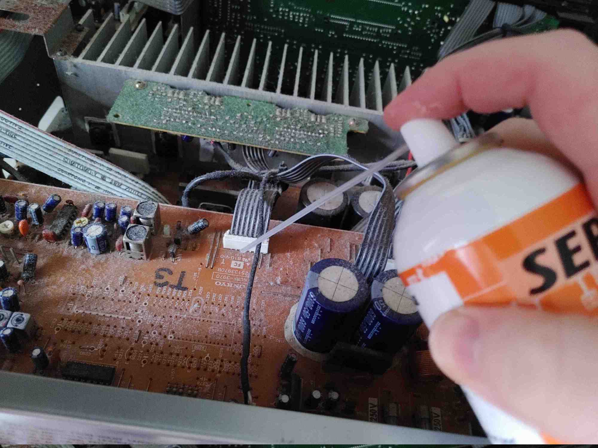
That said, I still decided to blow some compressed air onto it, just so any potential soldering wouldn’t also burn the dust.
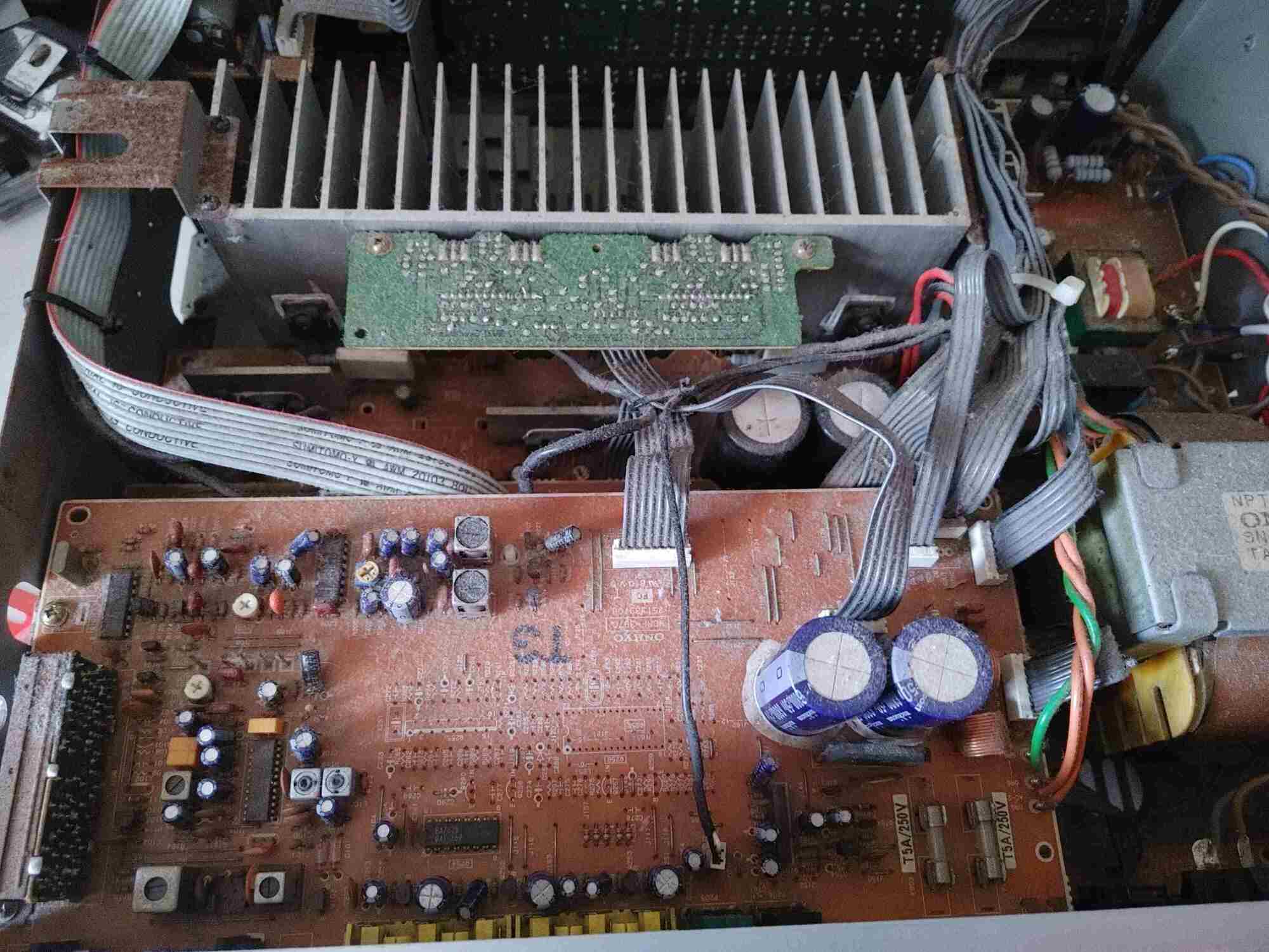
So there was only one board I actually needed to work on, and mercifully it was located near the top, so I didn’t have to take more things apart. However, I couldn’t get it out at all, and I couldn’t figure out why.
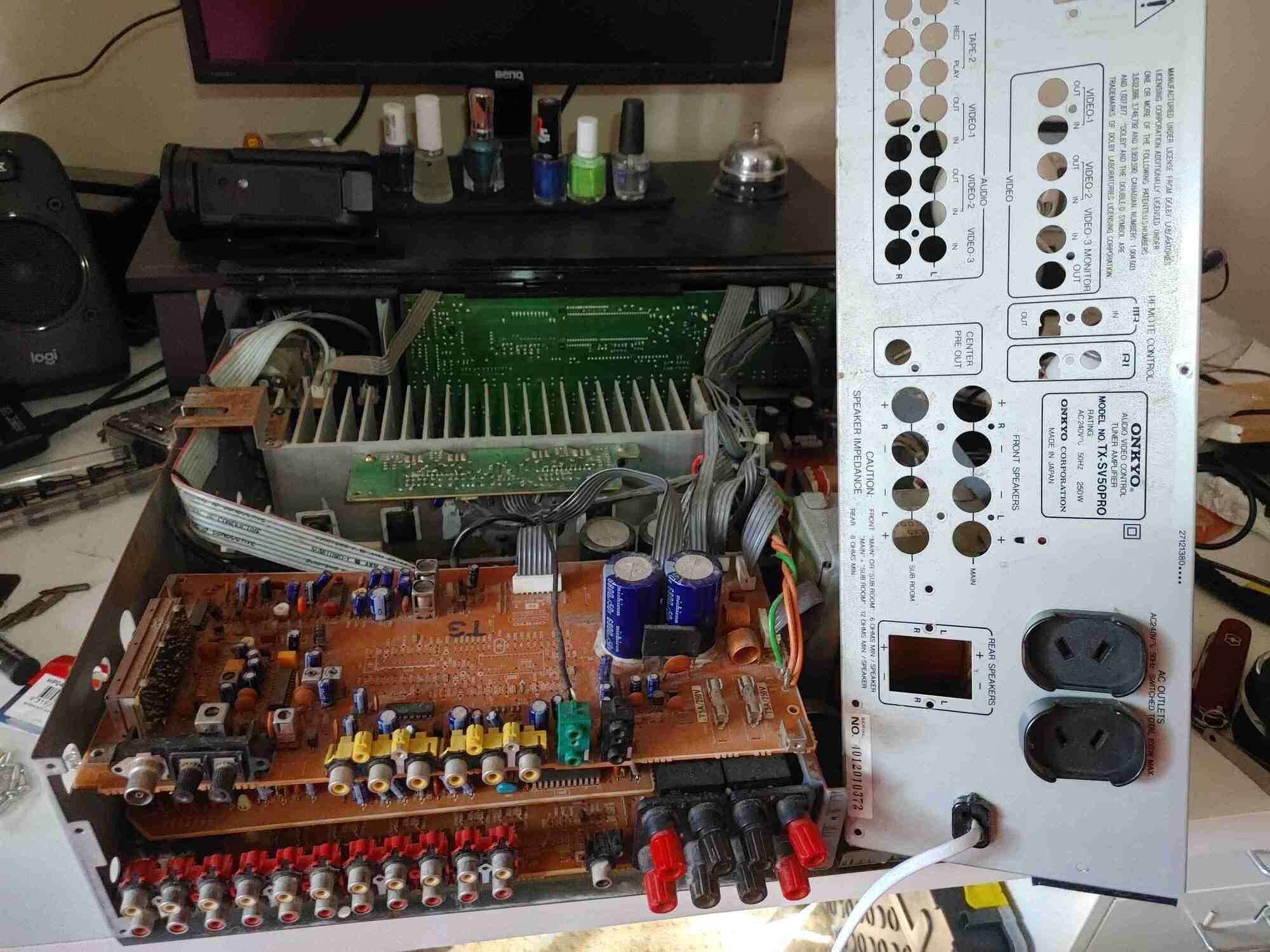
I even resorted to taking off the entire back cover, which proved to be unnecessary and quite annoying as we will see later. So what was it?
It was a peg, that I had somehow missed. Goddammit.
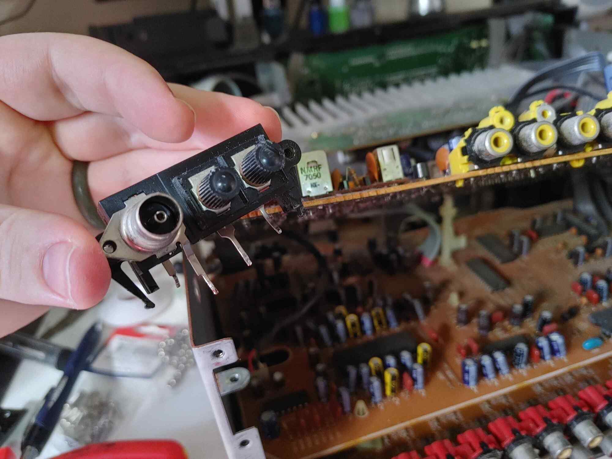
After dealing with that, I could finally get a proper look at the antenna inputs.
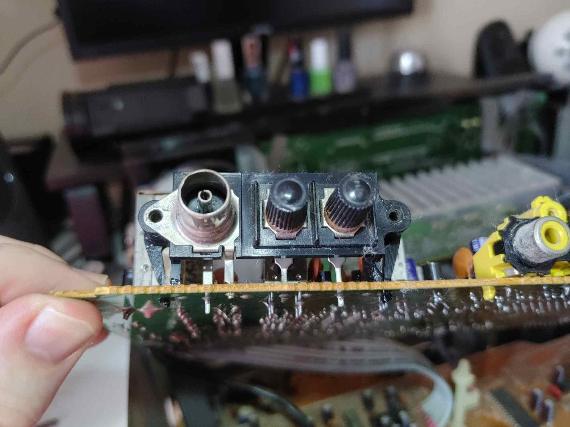
Thankfully it’s super simple, and I was able to remove it with some basic desoldering. What wasn’t so simple was actually getting the board in a position where I was able to do the desoldering in the first place, because the ribbon cables attaching it to the rest of the components were very stiff.
Cool!
So now we should see if the RCA jacks will fit in the case.
So close. However, the screwholes were misaligned by a fraction. Later on it will turn out that I didn’t need to worry about this at all, because I ended up supergluing the plate to the inside of the case anyway, but at this point, it was obvious that I had only one option.
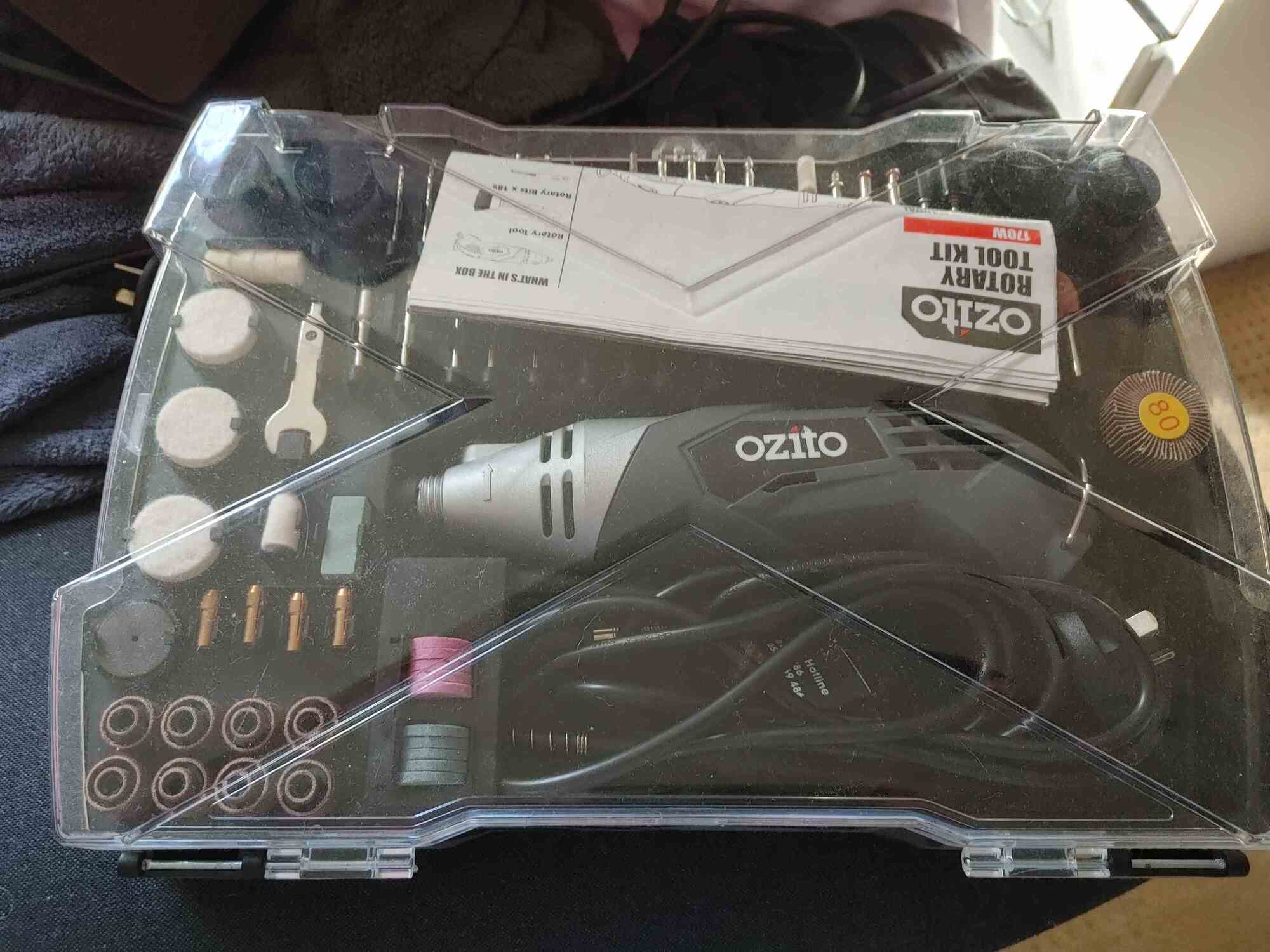
A rotary tool. I love this thing.
Several minutes of careful cutting later, and we get what is arguably a far uglier hole. Once again, it turns out that the screwholes were never going to be aligned anyway, so I just glued it in, but at least it was good practice. I guess.
Now for the real question. How the hell am I going to connect the RCA jacks to the tuner output?
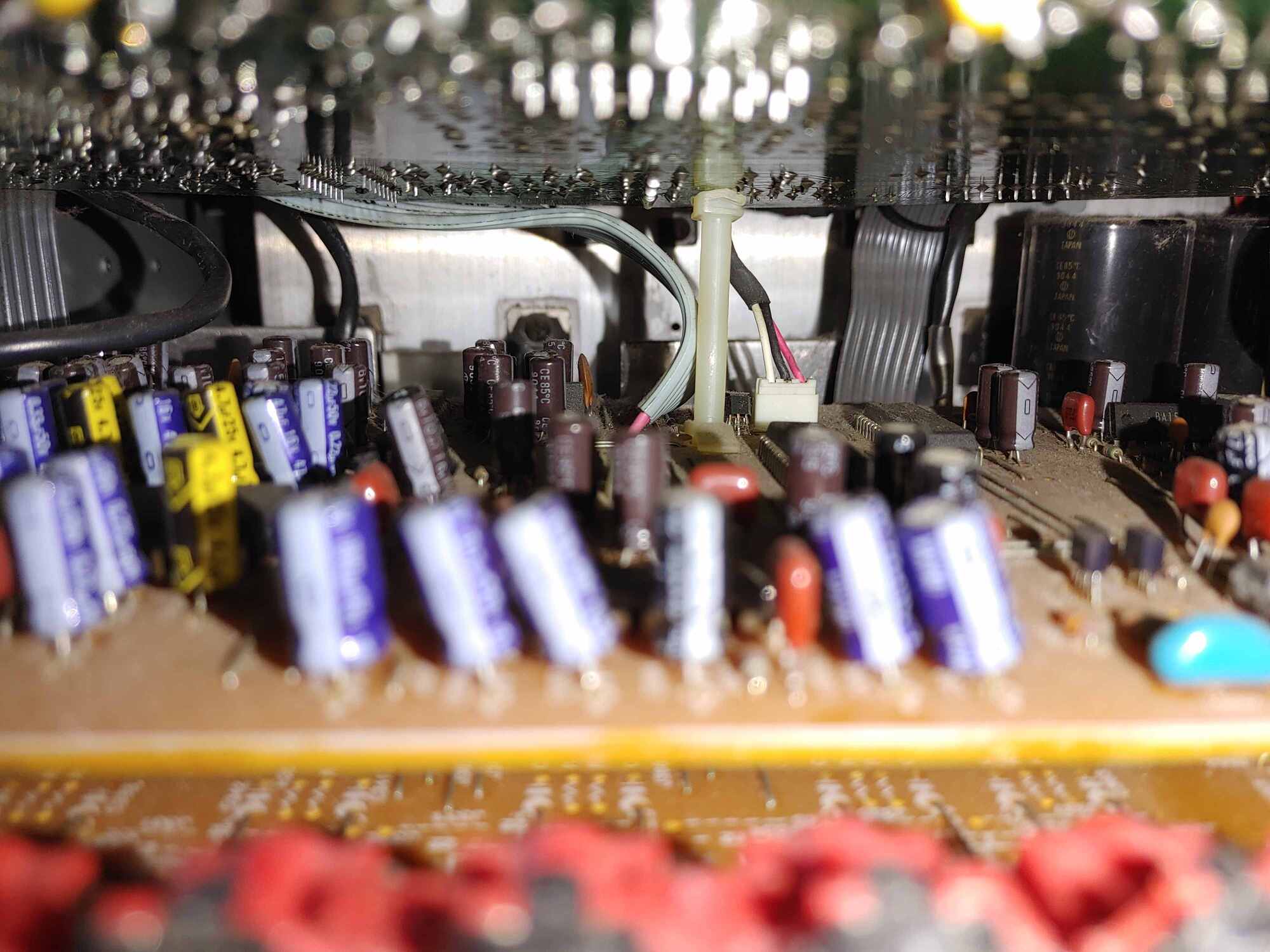
The amplifier board is completely separate to the tuner board, and is connected via several ribbon cables. One of these ribbon cables has two wires which each carry the demodulated radio signal to the amplifier, one for left, one for right. In order to get this to work, I’d have to cut the ribbon cable.
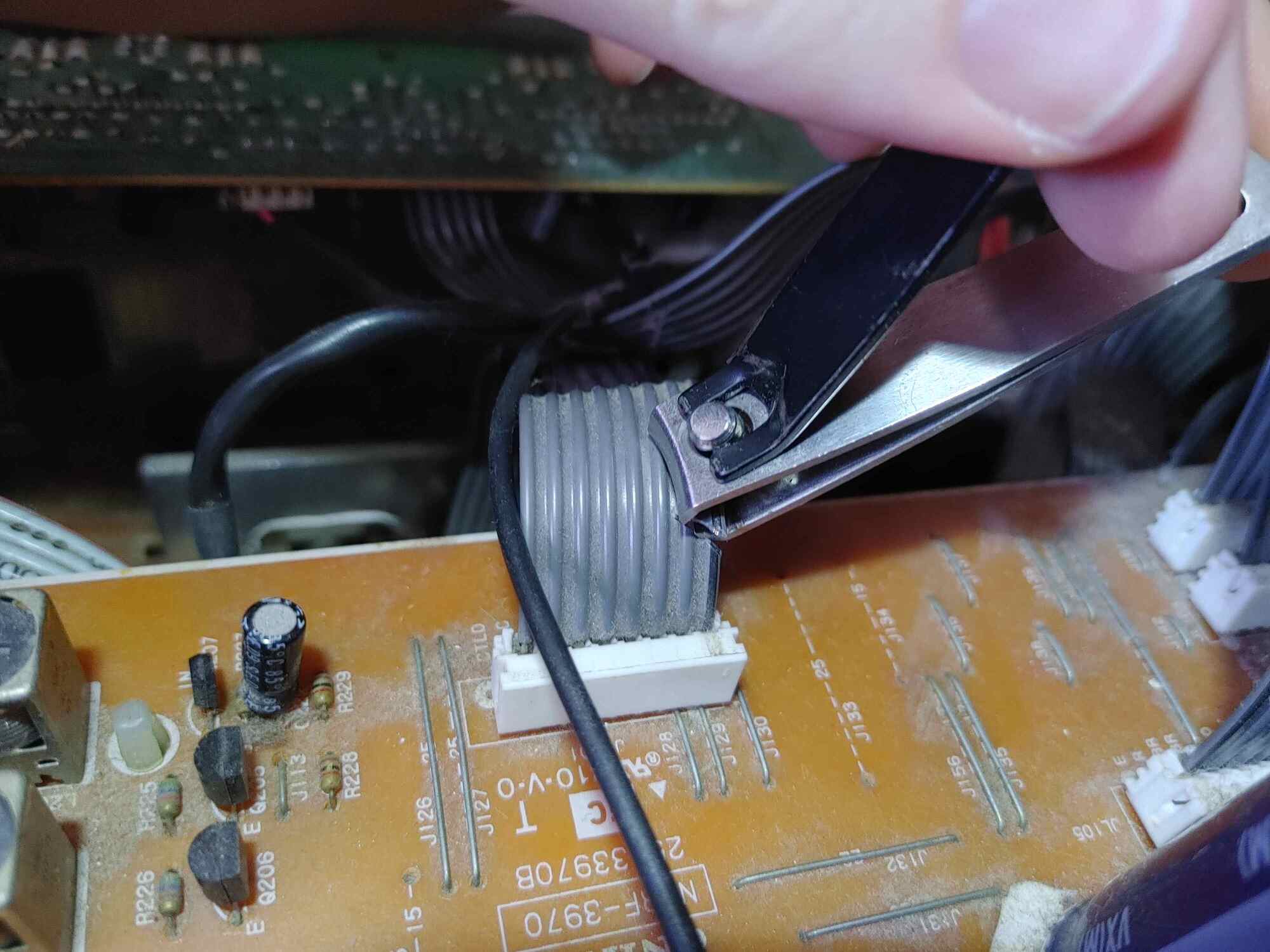
So that’s exactly what I did, using some nail clippers in order to get the job done.
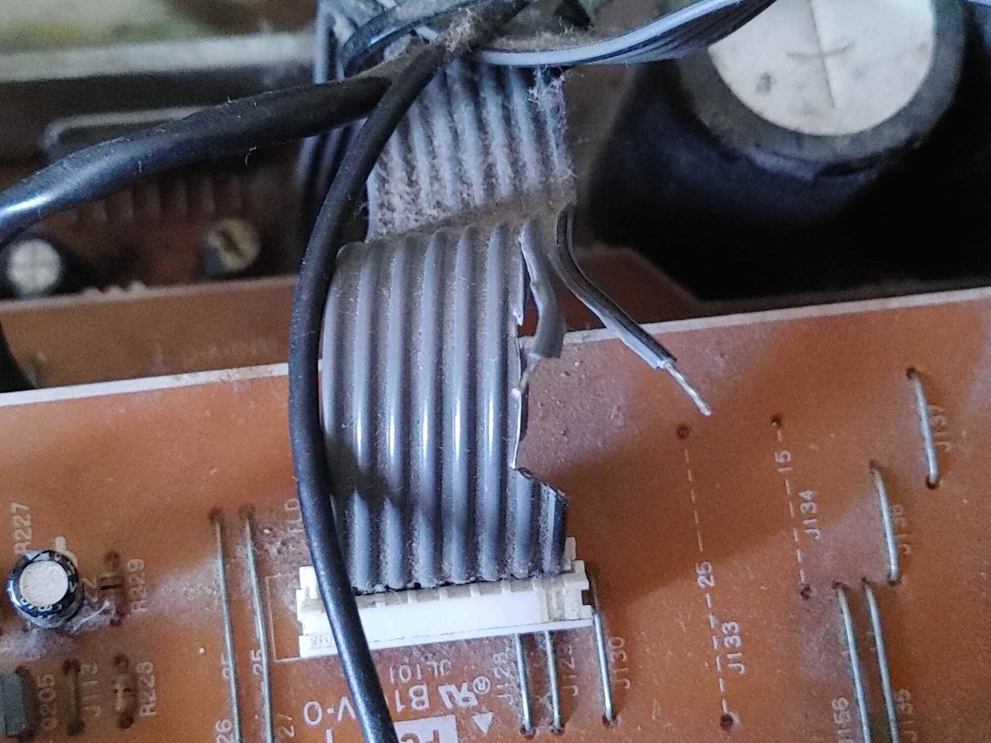
Here’s the two wires once they were freed. Each one carries an individual channel, so I needed to connect the RCA jacks to each of these, as well as to ground. Fortunately, due to the antennas also needing a ground connection, I didn’t have to go probing very far to find a ground.
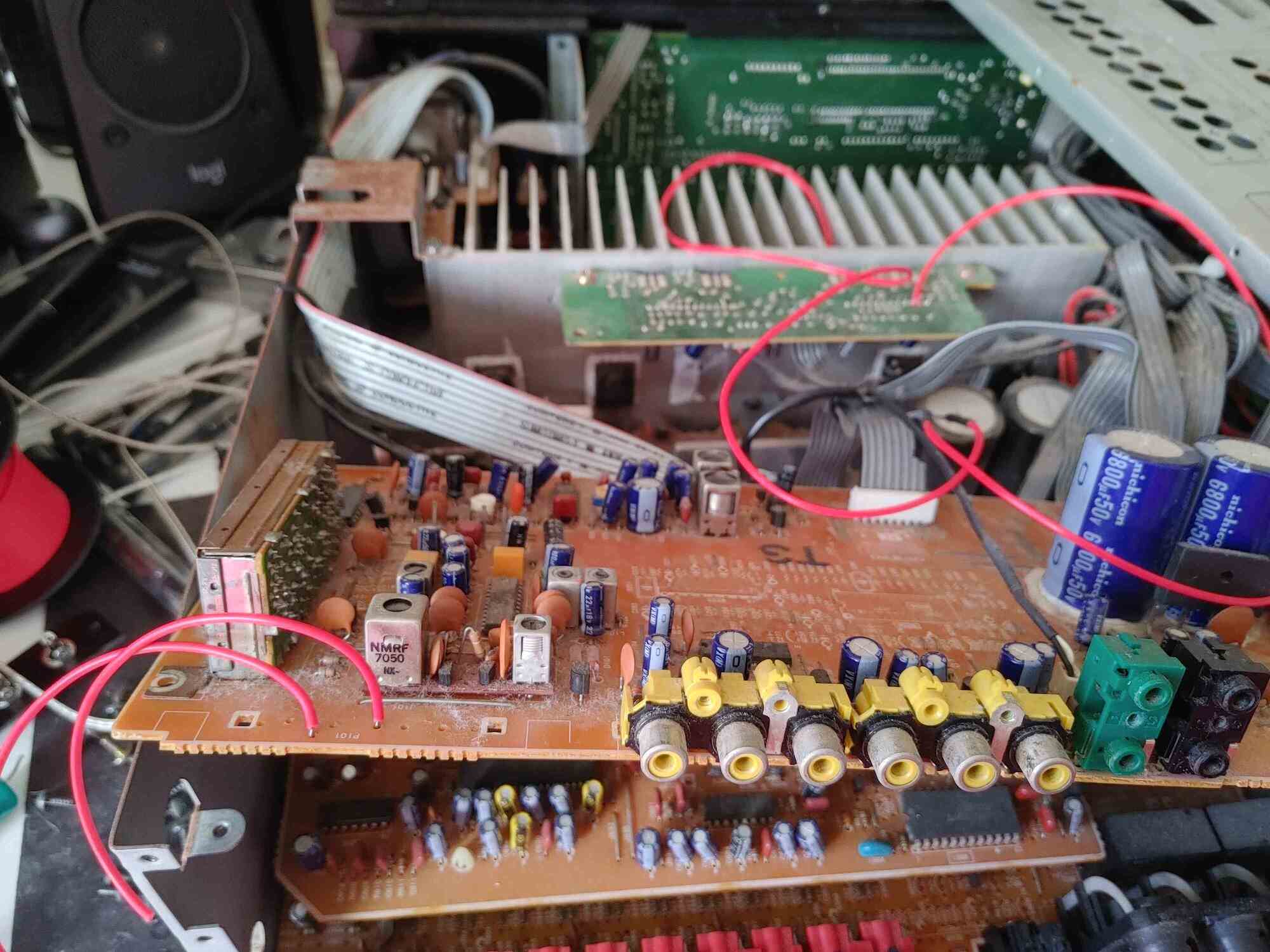
Soldering took an annoyingly long time, actually. I’m 99% sure this is because I was using lead-free solder, which doesn’t flow nearly as well as leaded solder. I should probably work on getting some leaded solder, but for now, this is all I’ve got.
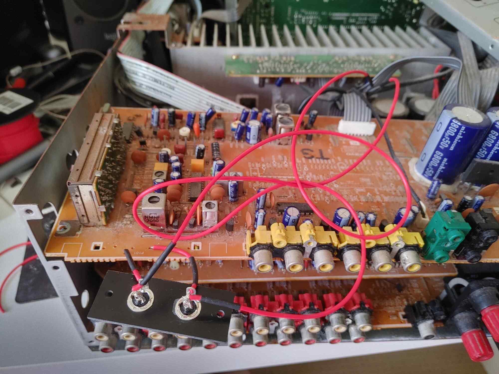
Thankfully, soldering the jacks didn’t take anywhere near as long, and soon everything was in place. All I needed to do was to put everything back together and hope nothing exploded.
Here’s the finished product! You can pretty easily tell that the RCA jack plate was glued on pretty messily, but professional work was very much not the name of the game here. All I wanted was something that would work.
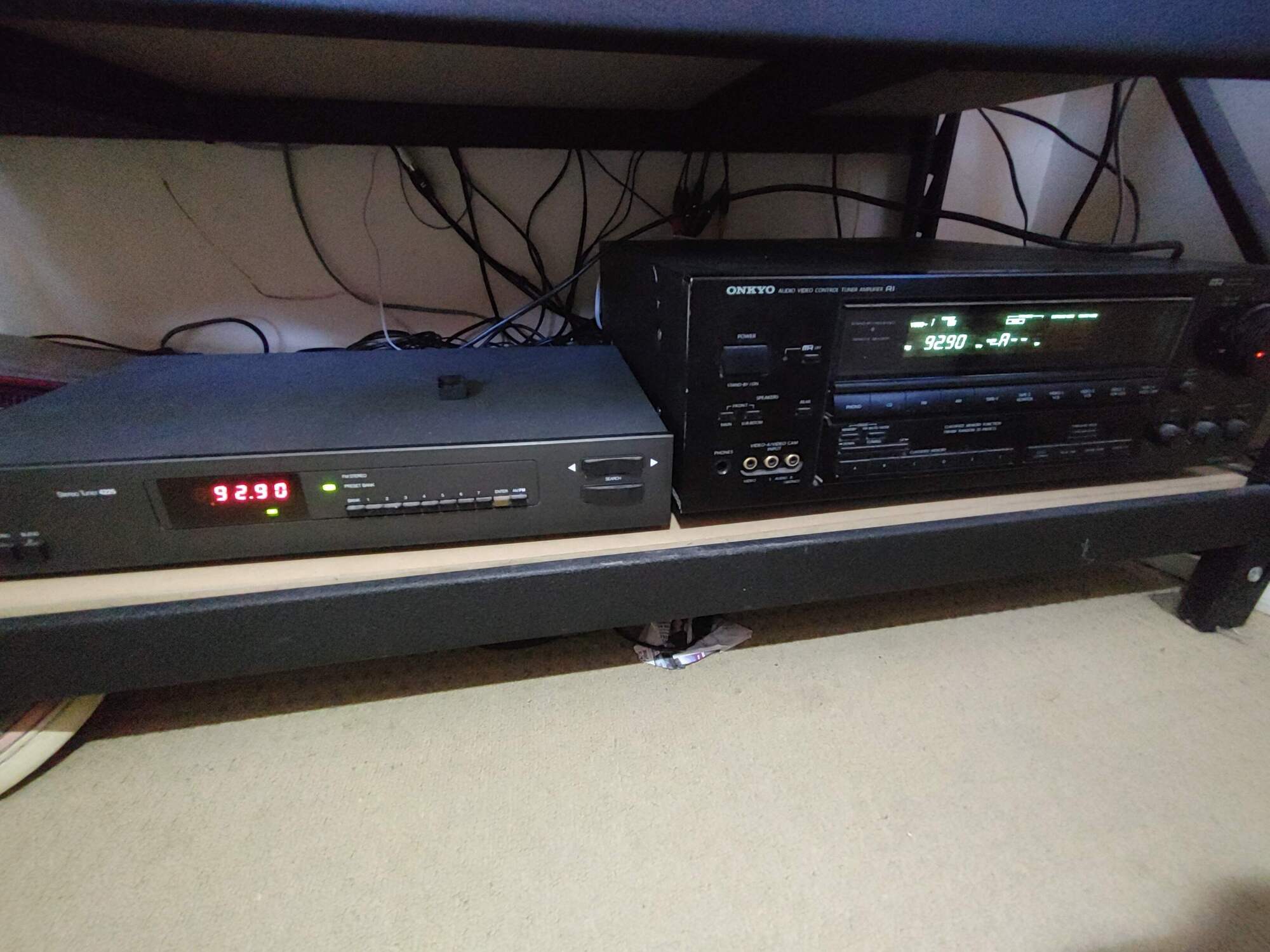
It totally works.
I should point out that although it shows the same station on both units, this is purely coincidental. The standalone tuner has no way of telling the receiver what station it’s receiving, all it can do is send the audio out. In fact, both the FM and AM buttons on the receiver are effectively identical.
Theoretically, one could hack the receiver further so that it didn’t show the station number, or it just said “RADIO” instead. Practically though, I’m not sure how possible this is. Hacking the firmware of the microprocessor is probably the best bet, but you would need to get a new processor to reprogram the ROM, since it cannot be reprogrammed. I don’t think it’s really that worth it, to be honest.
wait but why tho
So why did I do this? Was there any reason beyond simple annoyance at the bad tuner? Actually, yes. Analogue radio probably doesn’t have long for this world. FM radio broadcasting was shut down in Norway in 2017, with the entire country switching to digital radio. This was not without controversy, however it’s clear that it will die at some point. When that happens, the tuner inside the receiver would become completely useless, even if it worked properly.
However, now that I’ve replaced it with RCA jacks, I could easily swap out the old tuner with a new digital tuner instead. Alternatively, I could plug in a streaming box, or any number of devices. I’m not limited to simple analogue radio antenna connections, now I basically have anything I want.
Overall, I’m very pleased with myself! This was a really stupid idea when I thought about it yesterday, but then I actually managed to do it, so it became less stupid. Come back next week when I patch together a working space probe out of a knockoff PS1 Dualshock.